Abstract: Overhead cranes, also known as bridge cranes, are primarily used to lift heavy items in production workshops to meet production needs. During the lifting and lowering of items, energy is expended; if this energy can be reclaimed, it would significantly contribute to energy conservation, emission reduction, and green production. This plan proposes a transformation of the existing setup by using a variable frequency drive (VFD) and an energy feedback unit.
Keywords: INVT Goodrive300 VFD, Energy feedback RBU.
1. Project Background
Overhead cranes are widely used across various industries. Current traditional cranes mainly use AC contactors to control the forward and reverse rotation of each motor, thereby controlling movements such as advancing, retreating, lifting, and lowering. This control method has many drawbacks:
(1) The motor starts directly, resulting in a large inrush current. Frequent operation at high current generates significant heat, which shortens the motor's lifespan and affects power quality.
(2) Most overhead cranes operate under light loads, leading to a low power factor.
(3) High-speed operation or low speed ratios cause difficulties in positioning.
(4) When lifting heavy objects, the conservation of energy principle means that the object at a height has considerable energy, which is largely wasted as reactive power when lowered. This issue must be addressed in the context of building an energy-efficient society and reducing carbon dioxide emissions.
Given these drawbacks, is there a solution to address these issues? The application of a VFD combined with an energy feedback unit can effectively resolve these problems, ensuring smooth and energy-efficient operation of overhead cranes, accurate positioning, and improved power factor.
2. Solution Introduction
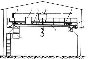
An overhead crane typically consists of a bridge (also known as the main trolley), a small trolley equipped with a lifting mechanism, a traveling mechanism for the bridge, a control room, and a conductive device for the small trolley. Figure 1 shows a schematic diagram of the overhead crane:

Fig. 1 Schematic Diagram of the Overhead Crane
1Bridge: Composed of the main beam, end beams, and walkways.
2. Main Trolley Traveling Mechanism.
3. Small Trolley.
4. Lifting Mechanism.
5. Control Room.
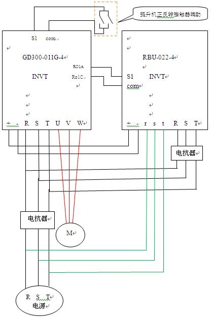
The solution utilizes the Goodrive300 series VFD to drive the motors, while the energy feedback unit (RBU) is responsible for energy recovery. The specific models will be selected based on the on-site motors and customer requirements. The energy-saving system diagram is shown in Figure 2.

Fig. 2 Energy-Saving System Diagram
3. Transformation Effects
Taking the customer site as an example, the operation after startup is smooth, with no hook drift or starting impact phenomena. Before the transformation, lifting 5 tons of steel required an ascending current of 15A and a descending current of 16A. After the energy-saving transformation, the ascending current was reduced to 7.5A and the descending current to 1.5A. Meter tests showed a 60% reduction in energy consumption, which made the customer very satisfied. They decided to install eight more units and will consider a full transformation if the initial operation remains problem-free.
4. Conclusion
The combination of INVT Goodrive300 series VFDs and INVT RBU for overhead crane lifting motors demonstrates significant energy-saving effects and excellent economic benefits. This solution is worth promoting widely across various organizations, contributing to energy conservation, emission reduction, and minimizing carbon dioxide emissions.


Our site uses cookies to provide you with a better onsite experience. By continuing to browse the site you are agreeing to our use of cookies in accordance with our Cookie Policy.